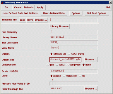
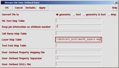
Now click the "User-Defined Data" button. In this window, specify the GDS layer map file and click OK.
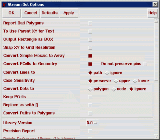
Now click Options. In this window, turn on "Convert PCells to Geometry" and click OK.
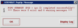
Now click Apply on the main "Stream Out" window. This will perform the export. If you didn't get any errors, you should see a window like the following.
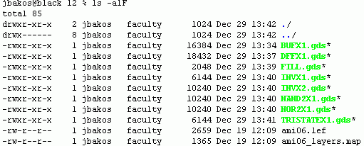
Repeat this procedure for each one of your layout cells. Do this for all of the cells you characterized with SignalStorm with the addition of the FILL cell. Note: in this tutorial, I also exported my non-pull tristate despite the fact that this was unnecessary as it will not be used in the synthesized netlist.
As you're converting, remember to change the GDS output filename immediately after you change or browse-to each cell name. The GDS output filename will not change automatically when you change the input cell name.
The goal here is to have a GDS file for each of your cells.
Using Abstract Generator
Now we need to start up Abstract Generator. Log in to a Solaris machine, change to your abstract work directory, and startup the tool by typing "abstract".
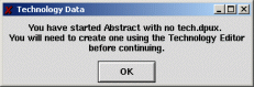
The first thing you'll see is the following window. Click OK.
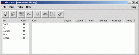
You will now see the main Abstract Generator window as well as a log window.
Creating Technology File
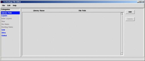
Select File | Technology. You will see the following window.
Select File | Load Lef File. Double-click "ami06.lef". Once the technology infomation is read from the LEF file, let's create a new Abstract Generator library.
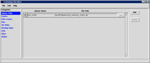
Replace the default "hldLib" library with "usc_scells" and set the path field to the path of your usc_scells library, but append "_ab" to the end of the path. For example, I used "/acct/f1/jbakos/cds_work/usc_scells_ab" for my path.
We don't want to give Abstract Generator the path to the "real" usc_scells library. If you do, Abstract Generator will do some very unfavorable things to your design data.
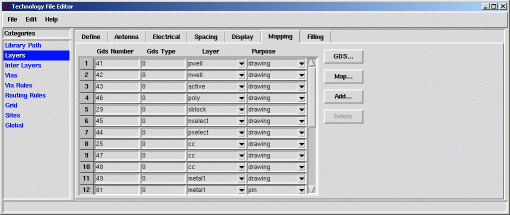
Now select the "Layers" section and go to the "Mapping" tab.
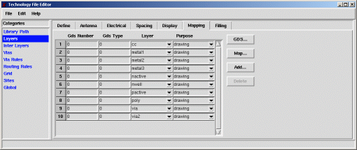
You'll notice here that our layers are defined under the "Layer" and "Purpose" column, but the "Gds Number" column is all zeros. The layer names came from the LEF technology file. We need to read in our GDS mapping file in order to associate each of the AMI C5N layer names with GDS layer numbers.
Click the "Map" button. A file open dialog will appear. Double-click the "ami06_layers.map" file. Once you do this, the GDS layer numbers will be shown for each layer name. You'll also notice additional layers that were added, corresponding to the layers specified in the map file that weren't present in the LEF file. These layers include pin layers.
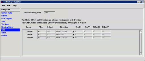
Select the "Grid" section. Make sure the Manufacturing Grid is set to .15 (half-lambda).
Set the pitch to be 4.5 and offset to be 2.25 for all three metal layers.
Now do a File | Save. When asked, save your new technology file as "tech.dpux". After this, do a File | Close.
Reading GDS Cell Layouts
Now we need to read in our GDS files. First, let's open our library.
Select File | Library.
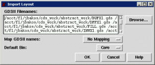
Next, select File | Import | Stream (GDSII). For each of your cells, click Browse and double-click the corresponding GDS file name. Once you've added all the GDS files for your cells, click OK.
Once you do this, your cells should be read into Abstract Generator.
There are three steps to complete in order to generate our abstracts: generating the pins view the extract view, and the abstract view.
- The pins step maps text labels to metal layers, associating certain metal blocks as pins.
- The extract merges metal blocks under the same net into one singla net.
- The abstract step copies the pin/net information from the extract step and generates obstructs for the metal and via layers.
Pins Step
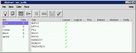
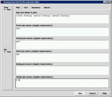
Let's perform the pins step. Select all of your cells and select Flow | Pins. Fill in the next window as shown and click Run.
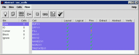
Your main Abstract Generator window should look as shown. If you received any errors or warnings (shown as 'X'- or '!'-symbols instead of the check-marks), select Cells | Report to view the report for each cell.
The FILL cell has a warning sign (!) because it doesn't have any input or output terminals. This is expected and thus not a problem.
Extract Step
Now let's perform the extract step. Make sure all the cells are selected and select Flow | Extract. The default settings will work. Click Run.
Now your main Abstract Generator window should look as shown. If you received any errors or warnings, select Cells | Report to view the report.

Abstract Step
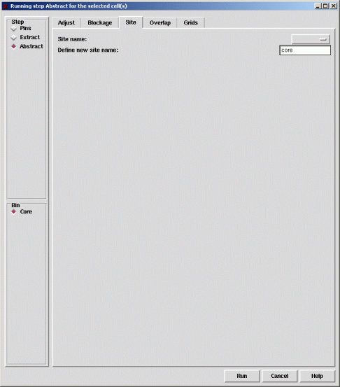
Now let's perform the abstract step. Make sure all the cells are selected and select Flow | Abstract. In the new window, click the Site tab and enter "core" under "Define new site name:".
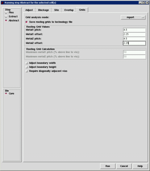
Now go to the Grids tab. Turn on "Save routing grids to technology file". Enter the routing grids, which is 4.5 pitch and 2.25 offset for both metal layers.
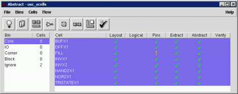
Click Run. This step will take some time to complete. Afterwards, your main Abstract Generator window should look as shown. If you received any errors or warnings, select Cells | Report to view the report.
Defining Symmetry
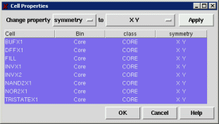
As a last step, make sure all your cells are selected. Select Cells | Cell Properties. Change "class" to "symmetry" and change "R0" to "X Y". Click Apply then OK.
You may also want to check out Cells | Terminal Properties. This will show you all your cell I/O terminals with their properties. However, there's nothing here you need to change.
Exporting Combined Technology/Abstract LEF File
Finally, select File | Export | LEF. Change the LEF filename to "usc_scells.lef" and click OK.
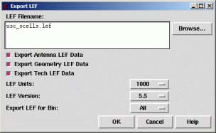
Your new LEF file contains both technology information as well as the abstracts (macros) for each of your standard cells. You may now exit Abstract Generator.
Creating Abstracts-Only LEF File
This LEF file is used for First Encounter, but we also need to import the abstracts into the Cadence IC-Tools. To do this, open usc_scells.lef into a text editor. Delete all the text between the following line...
MANUFACTURINGGRID 0.15 ;
...and the first line that begins with "MACRO". This effectively removes the technology information from the LEF file, leaving only the cell abstracts (macros).
Save the resulting file as "usc_scells_abstract.lef".
Importing Abstracts into Cadence IC-Tools
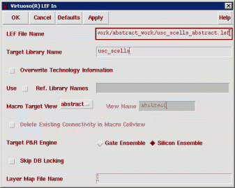
Back in the Cadence IC-Tools CIW, select File | Import | LEF. Type in the path for your abstracts-only LEF file ("usc_scells_abtsract.lef"), then type the name of the target library ("usc_scells"). Click OK.
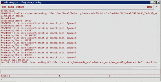
You will see the following warnings in your CIW window. It is okay to ignore them.
Note that this import procedure will not overwrite (or even modify) existing abstract views. Therefore, if you are performing this step after you've already imported your abstracts (for the purpose of correcting mistakes), you'll first need to delete all your existing abstract views one at a time using the Library Manager.
You will now see abstract views for each of your cells. As an example, open the abstract view for the INVX1 cell. You will see the cell border, pins, and metal1 route obstructs.
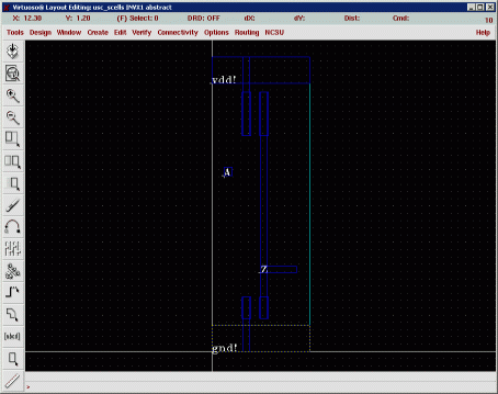
My DFFX1 cell also shows examples of metal2 route obstructs.
Fixing the Combined Technology/Abstract LEF File (usc_scells.lef)
There is at least one manual change that we must make to our combined technology/abstract LEF ("usc_scells.lef") file.
For some reason, Abstract Generator will not write the routing grid offset for the metal layers into the combined technology/abstract LEF file. We must enter this information manually or the place-and-route tool will refuse to route.
Open the combined LEF file ("usc_scells.lef") in a text editor. In the metal1 layer, metal2 layer, and metal3 layer LAYER section, insert the following line:
OFFSET 2.25 ;
Here's an example metal1 section. As you can see, I inserted the line after the PITCH line.
		LAYER metal1
		  TYPE		ROUTING ;
		  DIRECTION	HORIZONTAL ;
		  PITCH		4.5  ;
		  OFFSET	2.25 ;
		  WIDTH		0.9 ;
		  SPACING	0.9 ;
		  RESISTANCE	RPERSQ 0.09 ;
		  CAPACITANCE	CPERSQDIST 3.2e-05 ;
		END metal1
Also, make sure all of your clock inputs (CLK) are CAPITALIZED. If not, you can open the combined technology/abstract LEF file and replace "clk" with "CLK", although you should make this change in the original layout and repeat the entire Abstract Generator procedure.
That's all!